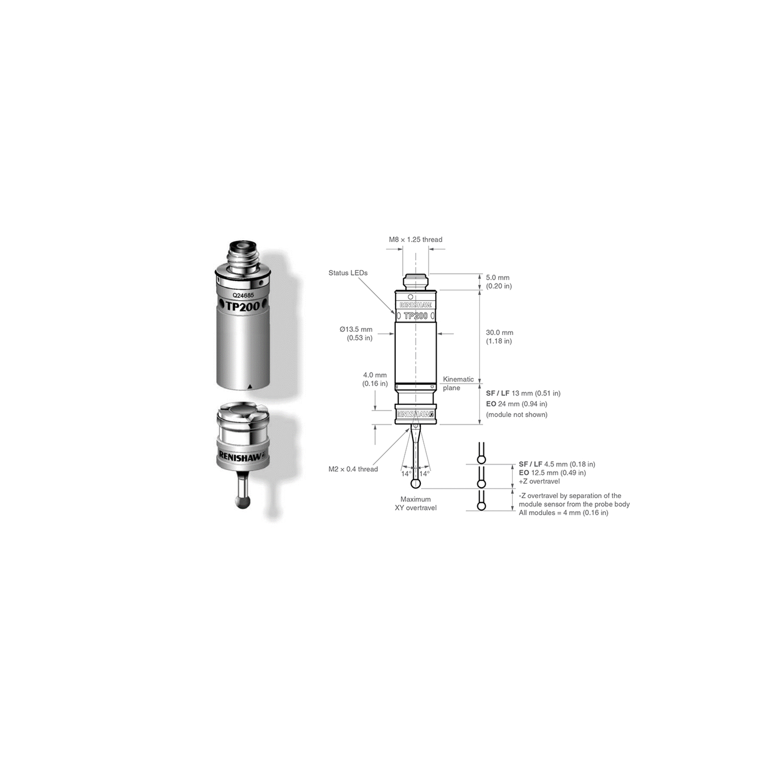
The TP200 system components are:
• TP200 probe body – the standard model
• TP200B probe body – a variant model with increased vibration tolerance
• TP200 stylus module – choice of fixed overtravel forces: ‘SF’ (standard force) or ‘LF’ (low force)
• PI 200 probe interface
• SCR200 stylus changing rack
TP200 probe body
The TP200 probe incorporates micro strain gage transducers delivering excellent repeatability and accurate 3D form measurement even with long styli. The sensor technology gives sub-micron triggering performance and eliminates the lobing characteristics encountered with standard probes. The solid state ASIC electronics within the probe ensure reliable operation over millions of trigger points.
TP200B probe body
The TP200B probe uses the same technology as TP200 but has been designed to have a higher tolerance to vibration. This helps to overcome the problem of ‘air’ trigger generation which can arise from vibrations transmitted through the CMM or when using longer styli with faster positioning speeds. Please note that we do not recommend the use of TP200B with the LF module or cranked/star styli.
Specification
| TP200 | TP200B | |
| Principal application | DCC CMM where high accuracy is required | As TP200 but where ‘air trigger’* events occur |
| Sense directions | 6-axis: ±X, ±Y, ±Z | 6-axis: ±X, ±Y, ±Z |
| Unidirectional repeatability (2σ µm) | ||
| Trigger level 1 | 0.4 µm (0.000016 in) | 0.4 µm (0.000016 in) |
| Trigger level 2 | 0.5 µm (0.00002 in) | 0.5 µm (0.00002 in) |
| XY (2D) form measurement deviation | ||
| Trigger level 1 | ±0.8 µm (0.000032 in) | ±1 µm (0.00004 in) |
| Trigger level 2 | ±0.9 µm (0.000036 in) | ±1.2 µm (0.000047 in) |
| XYZ (3D) form measurement deviation | ||
| Trigger level 1 | ±1 µm (0.00004 in) | ±2.5 µm (0.0001 in) |
| Trigger level 2 | ±1.40 µm (0.000056 in) | ±4 µm (0.00016 in) |
| Repeatability of stylus change | ||
| With SCR200 | ±0.50 µm (0.00002 in) max | ±0.50 µm (0.00002 in) max |
| Manual | ±1 µm (0.00004 in) max | ±1 µm (0.00004 in) max |
| Trigger force (at stylus tip) | ||
| XY plane – all modules | 0.02 N | 0.02 N |
| Z axis – all modules | 0.07 N | 0.07 N |
| Overtravel force (@ 0.5 mm displacement) | ||
| XY plane – SF / EO module | 0.2 N to 0.4 N | 0.2 N to 0.4 N |
| XY plane -LF module | 0.1 N to 0.15 N | 0.1 N to 0.15 N |
| Z-axis – SF / EO module | 4.90 N | 4.90 N |
| Z-axis -LF module | 1.60 N | 1.60 N |
| Weight (probe sensor and module) | 22 g (0.78 oz) | 22 g (0.78 oz) |
| Maximum extension (if on PH10 series head) | 300 mm (11.81 in) | 300 mm (11.81 in) |
| Maximum recommended stylus length (M2 styli range) | ||
| SF / EO module | 50 mm (1.97 in) steel to 100 mm (3.94 in) GF | 50 mm (1.97 in) steel to 100 mm (3.94 in) GF |
| LF module | 20 mm (0.79 in) steel to 50 mm (1.97 in) GF | 20 mm (0.79 in) steel to 50 mm (1.97 in) GF |
| Mounting method | M8 thread | M8 thread |
| Suitable interface | PI 200-3, UCC2-2 | PI 200-3, UCC2-2 |
| Stylus module changing rack | ||
| Automatic | SCR200 | SCR200 |
| Manual | MSR1 | MSR1 |
Above data applies for test conditions as follows: Stylus length 50 mm (1.97 in), stylus velocity 480 mm/min (1.57 ft/min)
* Air trigger (or false trigger). The TP200B reduces probe triggers that may be caused by vibrations.


